
97 Alloy
Two audio inputs fused through 15 crossfaded cross-modulation algorithms - ring mods, wavefolder, comparators, bitcrusher, frequency shifter, delay, binaural doppler, and a 20-band vocoder - with a clocked Turing machine driving pitch, CV, and gates underneath.
Panel
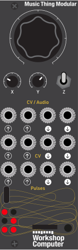 CarrierModulatorAlgorithm CVTimbre CVClockResetMainAux / RightTuring PitchTuring CVTuring Gate
ATuring Gate
B
Inputs
Outputs
Carrier
External carrier input
Modulator
Modulator input
Algorithm CV
Bipolar modulation added to the held Main value
Timbre CV
Bipolar modulation added to the held X value
Clock
External Turing clock; overrides the internal clock
Reset
Turing reset on rising edge
Main
Cross-modulated output
Aux / Right
Dry sum; doppler right channel, shifter opposite sideband, or bitcrushed dry mix in those zones
Turing Pitch
C-minor-pentatonic quantized pitch
Turing CV
Bipolar stepped modulation
Turing Gate A
First register bit gate
Turing Gate B
Length-aware second register bit gate
README
Alloy for Workshop System Computer
Alloy is a fixed-point cross-modulator, in the spirit of Mutable Instruments Warps and its parasites firmware, for the Music Thing Workshop System Computer. It combines 15 audio algorithms with a clocked Turing control layer that produces pitch, modulation CV, and two related gate patterns.
What's here
This card is self-contained and does not depend on anything outside its folder:
releases/97_alloy/
├── main.cpp              # hardware, control layers, and signal routing
├── CMakeLists.txt        # Pico SDK firmware build
├── ComputerCard.h        # Workshop System hardware abstraction
├── pico_sdk_import.cmake
├── dsp/                   # active integer DSP and control helpers
│   ├── xmod_engine.h      # 15-zone cross-modulation engine
│   ├── xmod_algorithms.h  # fixed-point algorithms
│   ├── vocoder.h, delay.h, frequency_shifter.h
│   └── turing_sequencer.h, tap_clock.h, soft_takeover.h
└── ...
The DSP is a fixed-point reimplementation of the Mutable Instruments Warps (and parasites) algorithms; the upstream float sources were used as design references but are not part of this repository.
Build and flash
From a configured Pico SDK environment:
cd releases/97_alloy
cmake -S . -B build -G Ninja
cmake --build build
This produces build/alloy.uf2 and build/alloy.elf. Flash either over SWD:
openocd -f interface/cmsis-dap.cfg -c "adapter speed 5000" \
        -f target/rp2040.cfg -c "program build/alloy.elf verify reset exit"
or copy the UF2 to a module in BOOTSEL mode (flash.ps1 waits for the
RPI-RP2 drive and copies it for you). The ComputerCard VS Code launch task
can also flash and attach through OpenOCD.
Performance
The active audio path is integer-only and runs at 48 kHz with a 240 MHz system clock (with the core voltage raised to 1.25 V). The vocoder splits its 20 bands across both cores. LED 4 latches if any sample exceeds the 20 us budget; LED 5 shows current headroom outside the Turing edit layer. The engine object is static because its delay buffers do not fit on the core-0 stack.
Current wiring
| Control | Mapping |
|---|---|
| Audio In 1 | External carrier |
| Audio In 2 | Modulator |
| Audio Out 1 | Cross-modulated output |
| Audio Out 2 | Dry sum; zone-specific aux in some zones (see below) |
| CV In 1 | Bipolar algorithm modulation |
| CV In 2 | Bipolar timbre modulation |
| Pulse In 1 | External Turing clock; overrides internal clock |
| Pulse In 2 | Turing reset on rising edge |
| CV Out 1 | C-minor-pentatonic Turing pitch |
| CV Out 2 | Bipolar Turing modulation |
| Pulse Out 1/2 | Length-aware Turing register gates |
Controls
Switch middle: cross-modulator
- Main: sweep 15 crossfaded algorithm zones.
- X: algorithm timbre.
- Y: per-zone third parameter where one exists; input drive elsewhere.
CV modulation remains live while these base values are held. After leaving the Turing layer, each knob uses soft pickup: its cross-mod value does not move until the physical knob reaches the value that was active before editing.
Switch up: Turing edit
- Main: OG-style feedback behavior. Fully right repeats exactly, center is maximally random, and fully left always inverts the feedback bit.
- X: sequence length: 2, 3, 4, 5, 6, 8, 12, or 16 steps.
- Y: output spread. Zero holds CV at its root/center; full scale spans four minor-pentatonic octaves and the full bipolar CV range.
- LEDs: show the first six active register bits.
Switch down: clock
Each press advances the sequence immediately. Two taps from 20–300 BPM start or update the internal clock. Hold down for 750 ms to stop it. A patched Pulse In 1 suppresses the internal clock; unplugging it resumes the tapped clock after one full period.
Algorithms
The Main knob sweeps 15 zones, crossfaded over the last quarter of each zone so most of the travel is the pure algorithm. Each zone's number is shown in binary on LEDs 0–3 (LED 0 is the least significant bit). Within a zone the Main knob's remaining travel drives a secondary "sweep" parameter where the algorithm has one. Y is input drive (10% floor, up to 2x with soft limiting) except in the three zones that repurpose it; Audio Out 2 is the dry input sum except in those same zones.
| # | Zone | X (timbre) | Y | Main sweep within zone | Out 2 | LEDs |
|---|---|---|---|---|---|---|
| 0 | Crossfade | carrier/modulator position (equal-power) | drive | — | dry sum | ○○○○ |
| 1 | Wavefold | fold amount | drive | fold bias (asymmetry) | dry sum | ●○○○ |
| 2 | Ring mod (analog) | post-diode gain (clean ring to saturation) | drive | — | dry sum | ○●○○ |
| 3 | Ring mod (digital) | ring gain into soft saturator | drive | — | dry sum | ●●○○ |
| 4 | Ring mod morph | digital-to-analog morph | drive | ring character (gain of both) | dry sum | ○○●○ |
| 5 | XOR | sum-to-XOR blend | drive | — | dry sum | ●○●○ |
| 6 | Comparator | 4-way morph: direct, threshold, window, window² | drive | — | dry sum | ○●●○ |
| 7 | Comparator-8 | 8-way morph through comparison/rectification combos | drive | — | dry sum | ●●●○ |
| 8 | Comparator + Chebyshev | comparator morph into a fixed ~T₅ waveshaper | drive | — | dry sum | ○○○● |
| 9 | Chebyshev | waveshaper order, continuous T₁–T₁₆ | drive | — | dry sum | ●○○● |
| 10 | Bitcrusher | bit-degradation amount | operator morph: sum, OR, XOR, shift | — | bit-degraded dry mix | ○●○● |
| 11 | Frequency shifter | shift, centre = none, quadratic to ±1 kHz | down/up sideband crossfade | feedback (barberpole) | opposite sideband | ●●○● |
| 12 | Echo delay | delay time, ~1 ms–340 ms | drive | feedback, up to ~95% | dry sum | ○○●● |
| 13 | Stereo doppler | x position (left-right) | depth (toward/away) | room size, tiny room to hall | right channel (main = left) | ●○●● |
| 14 | Vocoder | formant shift, centre = neutral | drive | envelope release time | dry sum | ○●●● |
| 15 | Vocoder freeze (pseudo-zone) | formant shift, centre = neutral | drive | — (release at end-stop) | dry sum | ●●●● |
The LED cells show the top two rows of the 2x3 LED grid as seen on the panel
(top row = LEDs 0 1, second row = LEDs 2 3, ● = lit): the zone number in
binary, LED 0 the least significant bit.
Row 15 is not a real selector zone but behaves like one: because the vocoder is the last zone, the top ~7% of the Main knob's travel (release past its end-stop threshold) freezes the spectral envelope - the carrier keeps playing through whatever formants were captured at that moment, and all four zone LEDs light. Backing off below the threshold resumes envelope tracking; CV into CV In 1 can cross the threshold rhythmically to gate freezes.
The bottom row is diagnostics: LED 4 latches if any sample ever exceeded the CPU budget, and LED 5's brightness shows live CPU headroom (bright = idle). With the switch up, all six LEDs instead show the Turing register bits.